NEEP602 Course Notes (Fall 1997)
Resources from Space
Lecture #8: You Can Get There from Here!
Title: Spacecraft Trajectories
September 19, 1997


Next: Lecture 9: Federal Funding of Civilian R & D
Previous: Lecture 7: Origin of the Solar System--Asteroids and Comets
Up: Resources from Space syllabus
Spacecraft trajectory overview
Spacecraft today essentially all travel by being given an impulse that places them on a trajectory in which they coast from one point to another, perhaps with other impulses or gravity assists along the way. The gravity fields of the Sun and planets govern such trajectories, and most of the present discussion treats this type of trajectory. Rockets launched through atmospheres face additional complications, such as air friction and winds.Advanced propulsion systems and efficient travel throughout the Solar System will be required for human exploration, settlement, and accessing space resources. Rather than coasting, advanced systems will thrust for most of a trip, with higher exhaust velocities but lower thrust levels. These more complicated trajectories require advanced techniques for finding optimum solutions, but a reasonably good approximate method will be given here.
Newton's laws of motion
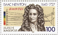
The fundamental laws of mechanical motion were first formulated by Sir Isaac Newton (1643-1727), and were published in his Philosophia Naturalis Principia Mathematica. They are:| Sir Isaac Newton | |
|---|---|
| 
|
Calculus, invented independently by Newton and Gottfried Leibniz (1646-1716), plus Newton's laws of motion are the mathematical tools needed to understand rocket motion.
Newton's law of gravitation
To calculate the trajectories for planets, satellites, and space probes, the additional relation required is Newton's law of gravitation:Every particle of matter attracts every other particle of matter with a force directly proportional to the product of the masses and inversely proportional to the square of the distance between them.
Symbolically, the force is
,
where and are the interacting masses (kg), is the distance (m) between them, and is a unit vector pointing between them. Kepler's laws of planetary motion The discovery of the laws of planetary motion owed a great deal to Tycho Brahe's (1546-1601) observations, from which Johannes Kepler [Note: Web link in German] (1571-1630) concluded that the planets move in elliptical orbits around the Sun. First, however, Kepler spent many years trying to fit the orbits of the five then-known planets into a framework based on the five regular platonic solids. The laws are:
- The planets move in ellipses with the sun at one focus.
- Areas swept out by the radius vector from the sun to a planet in equal times are equal.
- The square of the period of revolution is proportional to the cube of the semimajor axis. That is,
const
Conic sections
| In a central-force gravitational potential, bodies will follow conic sections. The equation for a conic section with the origin at one focus appears at top right, where e is eccentricity and a is the semi-major axis. | 
|

| |
| Special cases for conic sections are shown at right. E is the (constant) energy of a body on its trajectory. | 
|
| Conic section examples | 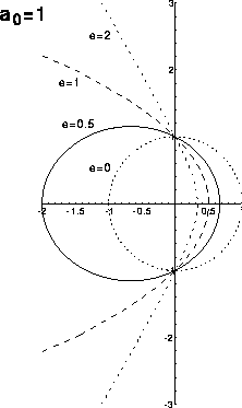
|
Some important equations of orbital dynamics
| Circular velocity | 
|
| Escape velocity | 
|
| Energy of a vehicle following a conic section, where a is the semi-major axis | 
|
| Clicking on the conic-section trajectory formulary thumbnail figure at right will show the main equations needed to define the position of a body at a given time. See text by Roy for definitions. |

|
Hohmann minimum-energy trajectory
Mars Global Surveyor
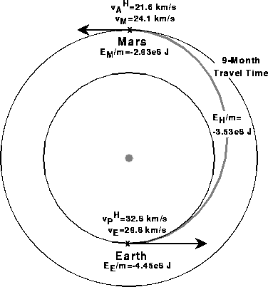
The Mars Global Surveyor mission arrived at Mars on September 11, 1997 and illustrates that the simple formulas given above are capable of estimating some important trajectory parameters within a few tens of percent. Selected parameters are shown in the following table
| Parameter | Hohmann trajectory | Mars Global Surveyor |
|---|---|---|
| Travel time | 8.4 months | 10 months |
| Velocity near Mars | 22 km/s | 24 km/s |
| Velocity difference with Mars | 2.9 km/s | 2.5 km/s |
The differences between the simple calculations and the actual values are due to somewhat a different trajectory than Hohmann for Mars Global Surveyor and neglected effects--such as the gravity of Mars. The Mars Global Surveyor Web page contains the color viewgraphs shown in class summarizing the mission trajectory, aerobraking, and further information on the instruments and other aspects of the mission.
Lagrange points
| The Lagrange (sometimes called Libration) points are positions of equilibrium for a body in a two-body system. The points L1, L2, and L3 lie on a straight line throught the other two bodies and are points of unstable equilibrium. That is, a small perturbation will cause the third body to drift away. The L4 and L5 points are at the third vertex of an equilateral triangle formed with the other two bodies; they are points of stable equilibrium. The approximate positions for the Earth-Moon or Sun-Earth Lagrange points are shown below. | 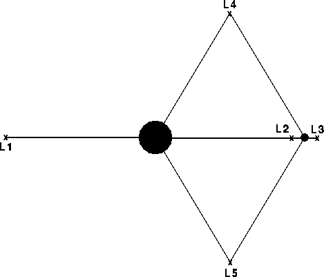
|
Rocket equation
Conservation of momentum leads to the so-called rocket equation, which trades off exhaust velocity with payload fraction. Based on the assumption of short impulses with coast phases between them, it applies to chemical and nuclear-thermal rockets. First derived by Konstantin Tsiolkowsky in 1895 for straight-line rocket motion with constant exhaust velocity, it is also valid for elliptical trajectories with only initial and final impulses. Conservation of momentum for the rocket and its exhaust leads to

| The rocket equation shows why high exhaust velocity has historically been a driving force for rocket design: payload fractions depend strongly upon the exhaust velocity, as shown at right. | 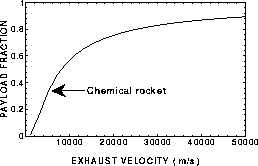
|
Gravity assist
| Gravity assists enable or facilitate many missions. A spacecraft arrives within the sphere of influence of a body with a so-called hyperbolic excess velocity equal to the vector sum of its incoming velocity and the planet's velocity. In the planet's frame of reference, the direction of the spacecraft's velocity changes, but not its magnitude. In the spacecraft's frame of reference, the net result of this trade-off of momentum is a small change in the planet's velocity and a very large delta-v for the spacecraft. Starting from an Earth-Jupiter Hohmann trajectory and performing a Jupiter flyby at one Jovian radius, as shown at right, the hyperbolic excess velocity is approximately 5.6 km/s and the angular change in direction is about 160o. | 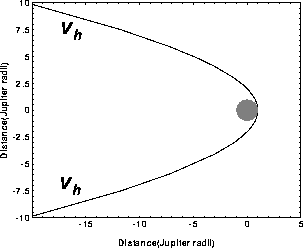
|
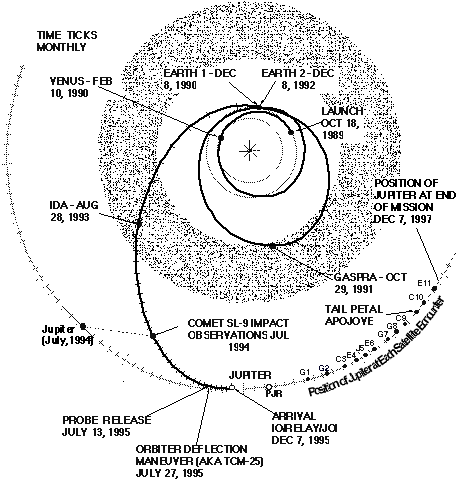
Galileo: a gravity-assist example
High-exhaust-velocity, low-thrust trajectories
The simplest high-exhaust-velocity analysis splits rocket masses into three categories:- Power plant and thruster system mass, .
- Payload mass, . (Note that this includes all structure and other rocket mass that would be treated separately in a more sophisticated definition.)
- Propellant mass, .
Useful definitions and relations
| Mission power-on time | tau |
| Total mass | |
| Empty mass | |
| Specific power [kW/kg] | 
|
| Propellant flow rate | 
|
| Thrust power | 
|
| Thrust | 
|
High-exhaust-velocity rocket equation
Assume constant exhaust velocity, , which greatly simplifies the analysis. The empty (final) mass in the Tsiolkovsky rocket equation now becomes , so![]()
where u measures the energy expended in a manner analogous to delta-v. After some messy but straightforward algebra, we get the high-exhaust-velocity rocket equation:
![]()
Note that a chemical rocket effectively has , and the Tsiolkovsky equation ensues. The quantity alpha*tau is the energy produced by the power and thrust system during a mission with power-on time tau divided by the mass of the propulsion system. It is called the specific energy of the power and thrust system. Relating the specific energy to a velocity through gives the definition of a very important quantity, the characteristic velocity:
 . The payload fraction for a
high-exhaust-velocity rocket becomes
![]() ,
,
which is plotted below.
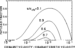
Analyzing a trajectory using the characteristic velocity method requires an initial guess for tau plus some iterations. The minimum energy expended will always be more than the Hohmann-trajectory energy. The payload capacity of a fixed-velocity rocket vanishes at , where . Substituting these values into the rocket equation gives

| Example: 9 month Earth-Mars trajectory (alpha=0.1 kW/kg, alpha tau=2x J/kg.) NB: When the distance travelled is factored into the analysis, only u>10 values turn out to be realistic. | 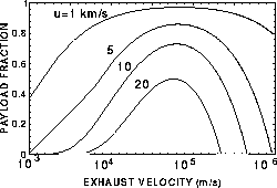
|
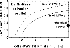
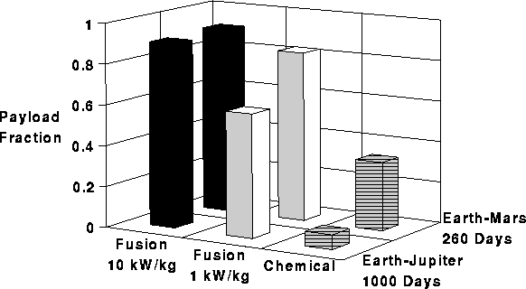
Trade-off between payload fraction and trip time for selected missions.
Variable exhaust velocity and gravity
Variable exhaust velocity and gravity considerably complicate the problem. When the exhaust velocity is varied during the flight, variational principles are needed to calculate the optimum . The key result is that it is necessary to minimize . Even the simplest problem with
gravity, the central-force problem, is difficult and requires advanced
techniques, such as Lagrangian dynamics and Lagrange multipliers. In
general, trajectories must be found numerically, and finding the optimum in
complex situations is an art.
Useful references
Astrodynamics
- Archie E. Roy, The Foundations of Astrodynamics (Adam Hilger, Bristol, 1988).
- John E. Prussing and Bruce A. Conway, Orbital Mechanics (Oxford Univ. Press, New York, 1993).
- Richard H. Battin, An Introduction to the Mathematics and Methods of Astrodynamics (AIAA, New York, 1987).
Low-thrust trajectory analysis
- Ernst Stuhlinger, Ion Propulsion for Space Flight (McGraw-Hill, New York, 1964).
- Krafft A. Ehricke, Space Flight: II. Dynamics (Van Nostrand, Princeton, 1962).
Related University of Wisconsin Courses
- EMA 550/Astron 550, Astrodynamics, is frequently taught each Fall semester and covers many of the topics discussed on this page plus celestial coordinate systems.
- EMA 601, Plasma Propulsion, is taught occasionally as a special topics course, most recently in Spring, 1997. It may be taught again if sufficient interest exists. Half of the course covers low-thrust trajectories and the other half treats plasma and electric thrusters (subject of lecture 31 in this course).
- EMA 742, Space Dynamics, is taught each Fall semester and covers spacecraft dynamics and stability.
Worldwide Web
- Space-related, government, and other potentially useful Web bookmarks
- 1996 Resources from Space related Web pages
- Lecture 28: Spacecraft Trajectories, which is similar to the present Web page.
- Lecture 29: Chemical Rockets
- Lecture 30: Plasma and Electric Propulsion
- Lecture 31: Fusion Propulsion
Questions
- What is the travel time from Earth to Saturn on a Hohmann trajectory?
- If a spacecraft is on an escape trajectory, what conic section does it follow?
- A satellite is in a circular, geosynchronous orbit around the Earth (mass = ). Assume that the terrestrial day is exactly 24 h and neglect the satellite's mass. Calculate the satellite's
- Geocentric radius (km)
- Velocity (m/s)
- Explain how high-exhaust-velocity, separately powered systems, even with their low thrust levels, can facilitate development of the Solar System.


Next: Lecture 9: Federal Funding of Civilian R & D
Previous: Lecture 7: Origin of the Solar System--Asteroids and Comets
Up: Resources from Space syllabus
Dr. John F Santarius
Fusion Technology Institute,
University of Wisconsin-Madison
1500 Engineering Dr.
Madison, WI 53706
USA
415 Engineering Research Building
e-mail: santarius@engr.wisc.edu; ph: 608/263-1694; fax: 608/263-4499
Last modified: September 22, 1997
 |
|
University of Wisconsin Fusion Technology Institute · 439 Engineering Research Building · 1500 Engineering Drive · Madison WI 53706-1609 · Telephone: (608) 263-2352 · Fax: (608) 263-4499 · Email: fti@engr.wisc.edu |
Copyright © 2003 The Board of
Regents of the University of Wisconsin System.
For feedback or accessibility issues, contact
web@fti.neep.wisc.edu.
|
