NEEP602 Course Notes (Fall 1997)
Resources from Space
Lecture #31: Charge!
Title: Plasma and Electric Propulsion
November 12, 1997
Next: Lecture 32: Fusion propulsion
Previous: Lecture 30: Chemical rockets
Up: Resources from Space syllabus
Selected events in the history of plasma and electric propulsion
| Year | People | Event |
|---|---|---|
| 1906 | Robert H. Goddard | Brief notebook entry on possibility of electric propulsion |
| 1929 | Hermann Oberth | Wege zur Raumschiffahrt chapter devoted to electric propulsion |
| 1950 | Forbes and Lawden | First papers on low-thrust trajectories |
| 1952 | Lyman Spitzer, Jr. | Important ion-engine plasma physics papers |
| 1953 | E. Saenger | Zur Theorie der Photonrakete published |
| 1954 | Ernst Stuhlinger | Important analysis. Introduces specific power |
| 1958 | Rocketdyne Corp. | First ion-engine model operates |
| 1960 | NASA Lewis; JPL | NASA establishes an electric propulsion research program |
| 1964 | USSR | Operate first plasma thruster in space (Zond-2) |
| 2002 | US | Possible solar-electric propulsion |
Plasma physics overview
A useful working definition of a plasma, taken from F.F. Chen,
Introduction to Plasma Physics, is
|
 |
Key equations and physical effects governing plasma behavior
Numeric formulas for many of the quantities discussed below are given in the Plasma Formulary in cgs units. SI units are used here.- Maxwell's equations for the microscopic electric (E) and magnetic (B) fields
- Lorentz force on a particle of charge q
- Plasmas Will Try to Reach Thermodynamic Equilibrium
- Plasmas are Dynamic Entities
- Debye Shielding
- Plasma Parameter The number of particles, N, in a Debye sphere (sphere with radius equal to the Debye length) must satisfy N>>1 in order for there to be statistical significance to the Debye shielding mechanism:
- Electrostatic potential sheaths
- Quantum mechanics and atomic physics
- Local thermodynamic equilibrium (LTE)
- High density plasma, so collisional effects dominate radiative ones.
- Characterized by the electron temperature, because electrons dominate the collisional processes.
- Coronal equilibrium
- Optically thin plasma
- Collisional ionization, charge exchange, and radiative recombination dominate.


The result of this equation is that charged particles spiral along
lines of magnetic force with the gyrofrequency (also called cylcotron
frequency)  at a distance called
the gyroradius (Larmor radius)
  ,
where
  is the average thermal velocity
of a particle. Because the electron's mass is much smaller than any ion's
mass, the electron gyrofrequency is much faster than the ion gyrofrequency
and the electron gyroradius is much smaller.
The Lorentz force leads to several charged-particle drifts, even in static electric and magnetic fields. These include drifts due to ExB motion, magnetic-field gradients, and magnetic-field curvature.
Neglecting boundary effects, equilibrium is represented by the Maxwell--Boltzmann or Maxwellian distribution of particles in energy,

where is the average charge density and Boltzmann's constant is J/eV. The latter value is given because it is often convenient to measure plasma energies and temperatures in electron volts, eV, rather than Kelvin, K (1 eV=11,604 K).
Electrons are extremely mobile. For example, the typical velocities for ions and electrons in a hydrogen plasma are

An important consequence of the high plasma mobility is Debye shielding, in which electrons tend to cluster around negative density fluctuations and to avoid positive density fluctuations. The Debye length, or Debye screening distance, gives an estimate of the extent of the influence of a charge fluctuation. It plays an extremely important role in many problems. The Debye length is given by

Click here for a derivation of the Debye length.

In general, the condition N>>1 is necessary for collective effects to be important.
Near any surface, and sometimes in free space, electron and ion flows can set up electrostatic potential differences, called sheaths. Commonly, these are approximately three times the electron temperature. Physically, sheaths set up in order to conserve mass, momentum, and energy in the particle flows. Sheaths repel electrons, which have high mobility, and attract ions. Free-space sheaths are called double layers.
Quantum mechanics enters the world of plasma thrusters because line radiation--the light emitted when electrons move down energy levels in an atom--can be a significant energy loss mechanism for a plasma. Other important phenomena include collisions and charge exchange (electron transfer between ions and atoms or other ions). Two important plasma regimes for radiation transport can be analyzed with relative ease:
High-Exhaust-Velocity Thrusters
Plasma and electric thrusters generally give a higher exhaust velocity but lower thrust than chemical rockets. They can be classified roughly into five groups, the first three of which are relevant to the present topic and will be discussed in turn.- Electrothermal
- Resistojet
- Arcjet
- RF-heated
- Electrostatic
- Ion
- Electrodynamic
- Magnetoplasmadynamic (MPD)
- Hall-effect
- Pulsed-plasma
- Helicon
- Photon
- Solar sail
- Laser
- Advanced
- Fusion
- Gas-core fission
- Matter-antimatter annihilation
- Tether
- Magnetic sail
Electrothermal thrusters
This class of thrusters (resistojet, arcjet, RF-heated thruster) does not achieve particularly high exhaust velocities. The resistojet essentially uses a filament to heat a propellant gas (not plasma), while the arcjet passes propellant through a current arc. In both cases material characteristics limit performance to values similar to chemical rocket values. The RF-heated thruster uses radio-frequency waves to heat a plasma in a chamber and potentially could reach somewhat higher exhaust velocities.Electrostatic thrusters (ion thrusters)
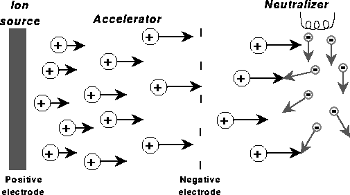
| This class has a single member, the ion thruster. Its key principle is that a voltage difference between two conductors sets up an electrostatic potential difference that can accelerate ions to produce thrust. The ions must, of course, be neutralized--often by electrons emitted from a hot filament. The three main stages of an ion-thruster design are ion production, acceleration, and neutralization. They are illustrated in the figure below. The basic geometry of an actual ion thruster appears at right on the cover from a recent Mechanical Engineering (from PEPL home page). |  |
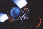
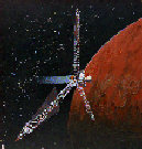
Two of artist Pat Rawling's conceptions of spacecraft using ion thrusters appear below. Fission reactors are located at the ends of the long booms in these nuclear-electric propulsion (NEP) systems. These and other designs are from NASA Lewis Research Center's now-defunct Advanced Space Analysis Office's (ASAO) Web page.
| NEP Mars approach | Hydra multiple-reactor NEP vehicle |
|---|---|
 |
 |
Electrodynamic thrusters
Magnetoplasmadynamic (MPD) thruster
In MPD thrusters, a current along a conducting bar creates an azimuthal magnetic field that interacts with the current of an arc that runs from the point of the bar to a conducting wall. The reulting Lorentz force has two components:- Pumping: a radially inward force that constricts the flow.
- Blowing: a force along the axis that produces the directed thrust.
 The basic geometry is shown at right in a frame from a computer
simulation done by Princeton University's Electric
Propulsion and Plasma Dynamics Lab. A movie of an MPD thruster, from
the PEPL,
can be accessed by clicking here.
Erosion at the point of contact between the current and the electrodes
generally is a critical issue for MPD thruster design.
Hall-effect thruster
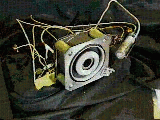 In Hall-effect thrusters, perpendicular electric and magnetic fields
lead to an drift. For a suitably chosen
magnetic field magnitude and chamber dimensions, the ion gyroradius is
so large that ions hit the wall while electrons are contained. The resulting
current, interacting with the magnetic field, leads to a
Lorentz force, which causes a plasma flow and produces thrust. The Russian
SPT thruster, shown at right, is presently the most common example of a
Hall-effect thruster.
Image source: University of Michigan Plasmadynamics and Electric Propulsion Laboratory
Pulsed-plasma thruster
In a pulsed-plasma accelerator, a circuit is completed through an arc whose interaction with the magnetic field of the rest of the circuit causes a force that moves the arc along a conductor.Helicon thruster
Useful references
Texts
General plasma physics
- Francis F. Chen, Introduction to Plasma Physics and Controlled Fusion (Plenum, New York, 1983).
- N.A. Krall and A.W. Trivelpiece, Principles of Plasma Physics (McGraw-Hill, New York, 1973).
- D. Nicholson, Introduction to Plasma Theory (Wiley, New York, 1983).
Plasma and electric thrusters
Note: These texts are still useful, despite having been written some years ago.- Robert G. Jahn, Physics of Electric Propulsion (McGraw-Hill, New York, 1968).
- Ernst Stuhlinger, Ion Propulsion for Space Flight (McGraw-Hill, New York, 1964).
Journals and conferences
- Journal of Propulsion and Power, American Institute of Aeronautics and Astronautics (AIAA).
- Journal of Spacecraft and Rockets, American Institute of Aeronautics and Astronautics (AIAA).
- IEEE Transactions on Plasma Science, Institute of Electrical and Electronics Engineers.
- AIAA/SAE/ASME/ASEE Joint Propulsion Conference
- International Electric Propulsion Conference
- NASA workshops on specific types of thrusters are held with fair regularity, and advanced-propulsion systems are often discussed in conferences devoted to long-range missions.
Note: Individual papers can be purchased from the AIAA, but proceedings are not published for these conferences.
Worldwide Web
Selected sites related to plasma and electric thrustersPresently, these do not contain a great deal of information, but they will undoubtedly develop and are worth keeping an eye on.
- Air Force Office of Scientific Research, Electric Propulsion Worldwide Web server
- University of Giessen (in German), I. Physikalisches Institut: Abt. Plasma- und Atomstoßphysik - Ionenquellen
- University of Michigan, Plasmadynamics and Electric Propulsion Laboratory
- Princeton University, Electric Propulsion and Plasma Dynamics Laboratory
- Stanford, Plasma Dynamics Laboratory
Questions
- Categorize and describe the three main types of plasma and electric thrusters.
- Describe the three main stages of an ion thruster.
- What two major forces are at work in the plasma plume of a magnetoplasmadynamic (MPD) thruster?
Next: Lecture 32: Fusion propulsion
Previous: Lecture 30: Chemical rockets
Up: Resources from Space syllabus
Dr. John F Santarius
Fusion Technology Institute,
University of Wisconsin-Madison
1500 Engineering Dr.
Madison, WI 53706
USA
415 Engineering Research Building
e-mail: santarius@engr.wisc.edu;
ph: 608/263-1694; fax: 608/263-4499
Last modified: Tue Jul 21 16:58:25 CDT 1998
 |
|
University of Wisconsin Fusion Technology Institute · 439 Engineering Research Building · 1500 Engineering Drive · Madison WI 53706-1609 · Telephone: (608) 263-2352 · Fax: (608) 263-4499 · Email: fti@engr.wisc.edu |
Copyright © 2003 The Board of
Regents of the University of Wisconsin System.
For feedback or accessibility issues, contact
web@fti.neep.wisc.edu.
|
